
There are multiple reasons why you want to change your final drive. If you have an OEM final drive, you probably want to increase reliability and lifetime. If you already have a motorsport final drive, you probably want to create the perfect gearing for your car and track. Both reasons are highlighted below.
Final Drive Ratio
Choosing your right gearing is all about ‘compromise’. A lower (taller) gear ratio provides a higher top speed, and a higher (shorter) gear ratio provides faster acceleration. . Besides the gears in the transmission, there is also a gear in the rear differential. This is known as the final drive, differential gear, Crown Wheel Pinion (CWP) or ring and pinion.
In the table below you can see the top speed in each gear for different final drive ratio’s. If you want to know the car details such as maximum RPM and gear ratio’s, click .
BMW E92 – DG400 Gearbox
| Max. Rpm | 8000 | RPM | |
| Wheel R | 311,5 | mm | |
| Gear | Prim. | Sec. | Ratio |
| 1 | 13 | 37 | 2,84 |
| 2 | 15 | 32 | 2,13 |
| 3 | 16 | 28 | 1,76 |
| 4 | 18 | 27 | 1,50 |
| 5 | 21 | 27 | 1,28 |
| 6 | 23 | 26 | 1,13 |
| FD | 11 | 45 | 4,10 |
| Gear | Final drive ratio | ||
| 4.10 | 4.75 | 5.28 | |
| 1st | 81 | 70 | 63 |
| 2nd | 108 | 93 | 84 |
| 3rd | 130 | 112 | 101 |
| 4th | 153 | 132 | 119 |
| 5th | 179 | 155 | 139 |
| 6th | 203 | 175 | 158 |
| Torque increment | 0% | 15,8% | 28,7% |
You can see the reduction of top speed (from 203km/h to 158km/h), while the acceleration torque increases (28,7%). As said before, it’s all about compromises. You are sacrificing either torque for top speed, or top speed for torque.
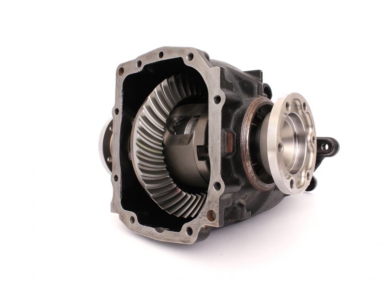
Motorsport Final Drive
The OEM final drives are designed for the specifications of that specific car. If you are upgrading your car, or increasing engine power, the OEM parts of the drivetrain will have a higher failure risk. Upgrading your drivetrain components is necessary, since a chain is only as strong as its weakest link.
Characteristics of a Motorsport Final Drive
- Cyclo palloid gear shape
- Small batches
- High-grade steel
- Custom ratio’s
- More strength in same package size
In the next blog the differences between Gleason, Klingelnberg and Oerlikon gear shapes and manufacturing will be explained. Please comment or share if you would like to read more blog posts on this subject! If you want to find out more technical specification on final drives, please consult the catalog.
A CAN-Bus protocol is designed to allow different devices to communicate with each other. This kind of communication is widely used in the Motorsport world. Now, there is a lot of (technical) information available on the internet. In this blog I will give you practical tips on how to use and test this for motorsport purposes.
Tip #1: Measure the resistance
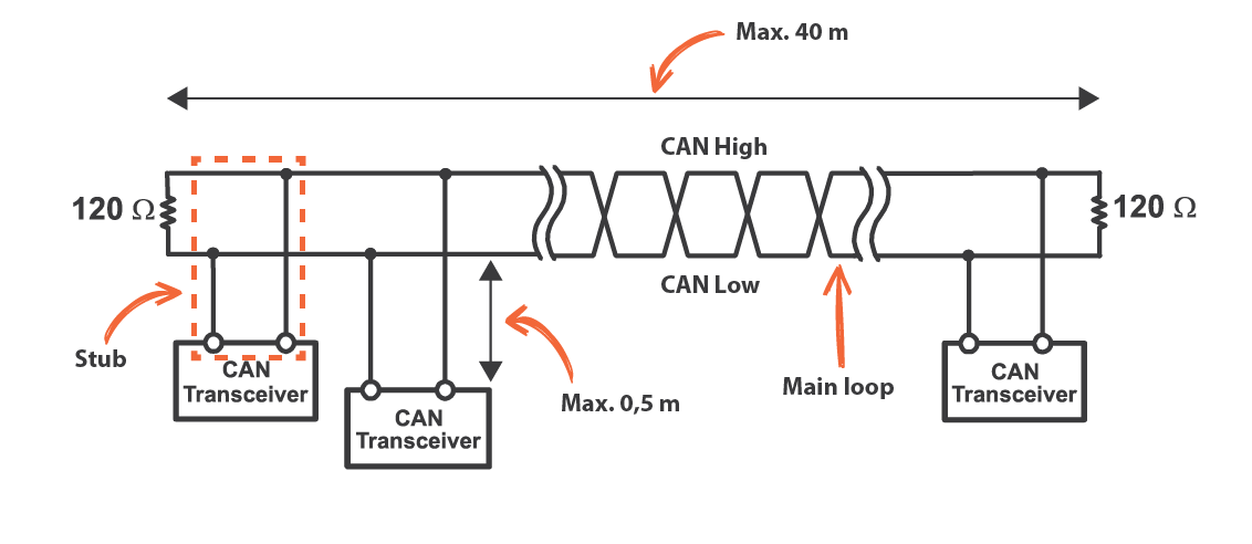
The most common CAN-Bus issue is too much or too little termination resistance. In a low speed CAN each device should have a 120 Ohm resistor. In a high speed CAN-Bus (>100Kbit, used in automotive) only each end of the main loop should have a 120 Ohm resistor. Measure with a multi-meter the resistance between CAN-High and CAN-Low. Make sure the power supply is completely turned off. You should measure 60 Ohms over these 2 wires, because there are two 120 Ohms resistors in parallel (parallel resistance calculator). If there are 3 resistors in the wiring, you will measure 40 Ohms, and with 4 resistors you will measure 30 Ohms. Some devices have an internal resistor, but mostly these resistors are integrated in the wiring harness.
Tip #2: Check the speed of each device
In Motorsport, there are usually two (bitrate) speeds used: 500kbit/s or 1Mbit/s. As a rule of thumb 1Mbit/s can have a maximum cable length of 40 meters, where a 500kbit/s can have 100 meters. Try not to exceed 0,5 meter for each stub. If the stub is too long, it will result in data losses or error messages. From practical experience, most OEM CAN devices are at 500kbit/s. Motorsport devices are often set at 1Mbit/s. Always make sure you know the settings of each device connected to the CAN-Bus, or it will crash the communication. All devices need to run at the same speed.
Tip #3: Measure the voltages
Most of the time you will have a pin-out from a device (such as an ECU or display), so you can trace down the correct wire. But if you don’t have a pin-out, and you are not 100% sure which wire is CAN-High or CAN-Low, you can measure the voltage of each wire. The CAN High wire usually fluctuates between 2.5V and 3.5V. The CAN-Low wire usually fluctuates between 2.5V and 1.5V. If you do not have a oscilloscope, you can measure the average voltage with a multi-meter. You will measure around 2,2V for CAN-Low and 2,7V for CAN-High.

Tip #4: Check the CAN-Bus load
There are several dedicated CAN-Bus monitoring tools available (such as Kvaser or PCAN-USB) which can show all raw CAN messages and bus load. Some ECU’s or Displays have this kind of monitoring tools integrated as well. From own experience you need to try to stay below 60-70% load. You have a possibility of data loss or errors if you go above it. If you need to add more messages to the CAN-Bus, try to reduce the update frequency of some messages, or connect a second CAN-Bus.
Tip #5: Use multiple CAN-Busses
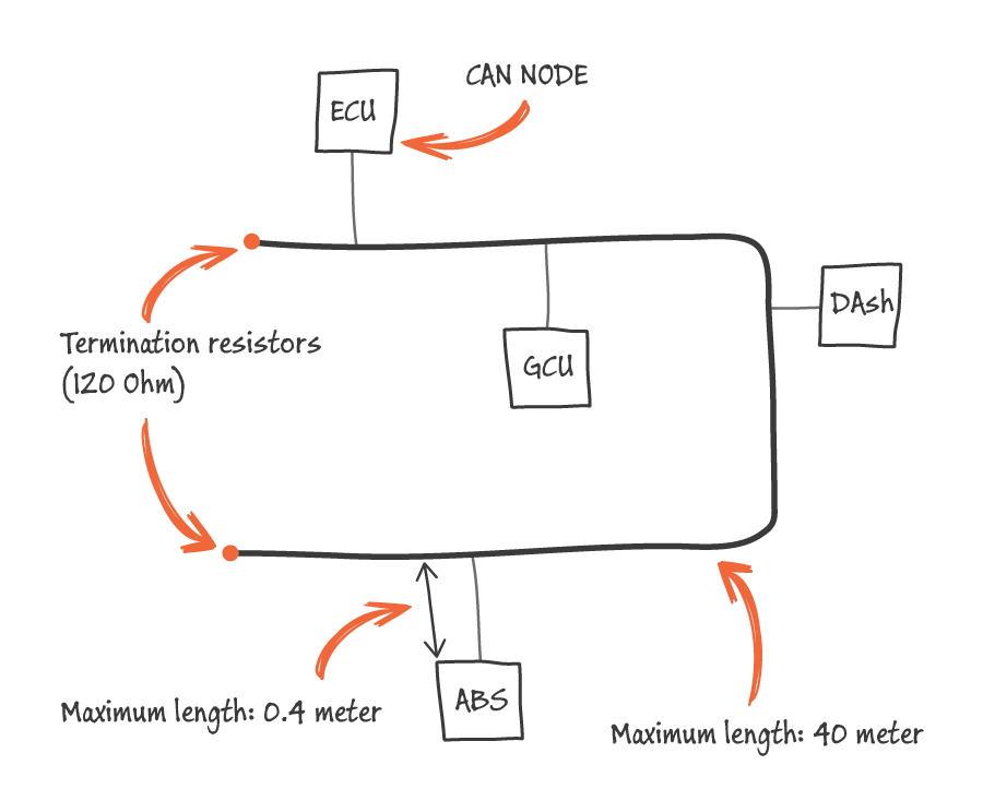
This is one of the most unknown/unused safety features in Motorsport. Put all important devices (ECU/Display/GCU/ABS) on 1 bus, and all secondary devices such as cameras or other ‘unimportant’ devices on a second CAN-Bus. Most of the latest generation ECU’s and Displays have more than a single CAN-Bus. This will give you the possibility to receive signals on the first bus, and sent out on a second if needed. If a device such as a camera crashes the CAN-Bus, all important devices will still continue to work, and you can finish your race.
Overview:
- 120 Ohms on end of bus (only 2x 120 Ohms)
- Make sure all devices have the same bitrate speed
- Measure voltage of CAN-High and CAN-Low
- Do not exceed 60-70% CAN-Bus load
- Use multiple CAN-Busses to avoid communication errors
Thank you for reading this blog. If you would like to get more blogs on this subject, please share or comment below!
In this post I will explain the very basics of a CAN-Bus network which is used in Motorsport vehicles. This can be helpful for people who ever heard of the name, but never knew what it is or what is does. There is a lot of technical information on the internet, but my goal is to explain it in very basic language. In this post I’m taking a High-speed (1mbit/s) CAN2.0A 11-bit specification as example.
CAN stands for Controller Area Network. It is a method to allow microcontrollers to communicate with each other in a network (bus). Compare it to Ethernet (LAN), a standard to allow computers to communicate with each other as well.
CAN-Bus Hardware
The bus line is a twisted pair wire with a termination resistor (120 Ohm) on each side. One wire is called CAN High and one wire is called CAN Low. Both wires are needed for proper communication.
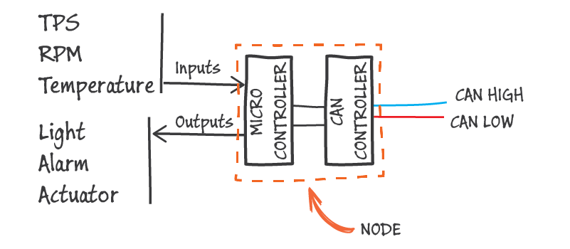
A device which is connected to the bus is called a ‘Node’. There are always two or more nodes required on the CAN network to communicate. In Motorsports you will usually find 3 to 10 nodes on the bus.
A node has at least a Micro Controller and a CAN Controller integrated. The CAN Controller converts digital information to messages on the bus. Compare it to Morse code. Information comes in, the CAN Controller translates it and sends out the message in a defined language, and another CAN Controller receives the information again.
A Micro Controller will process information such as sensor inputs or outputs to turn on lights or an actuator. The Micro Controller can also process information to control a dashboard or another kind of communication.
CAN-Bus messages
A CAN-Bus message holds all kind of data, but the basics are an ID and a message frame (8 bytes). Imagine it as a train: The train goes with a certain speed (1Mbit/s) over the rail (bus), and has several wagons (ID’s). At every train station (Node) you can put more wagons on the train, or see who’s in another wagon. The wagon (ID) with the lowest number, has the highest priority and comes first. A Node can sent multiple ID’s on the bus.
A wagon (ID) has 8 private rooms (bytes) with each 8 seats (bits). Each seat (bit) can have a value of 0 or 1. A complete private room with 8 seats can have 256 different combinations, which is the maximum value of 1 byte. In normal language; 1 ID can hold multiple signals such as RPM, Throttle, Temperature etc. If each signal is on 1 Byte (8 bits), the ID can hold 8 signals.
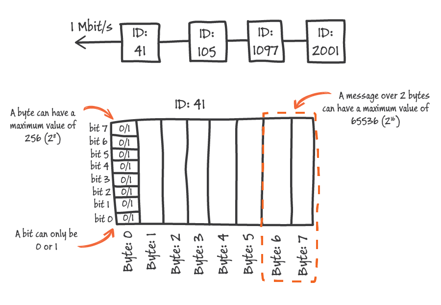
If you want to send out a message as ‘8000 RPM, the maximum accuracy of 1 room (byte) will be 5000 mV / 256 = 31 RPM. The signal transmitting will go in steps of 31 RPM. To get higher accuracy, it is possible to use 2 rooms (bytes) for 1 message. Two rooms can have a maximum value of 62236. If you send out a message ‘8000 RPM’ over 2 bytes, the steps will be 8000 / 65536 = 0,12 RPM.
It is important to understand why sometimes 1 bit, 1 byte or 2 bytes are used to transmit a signal.
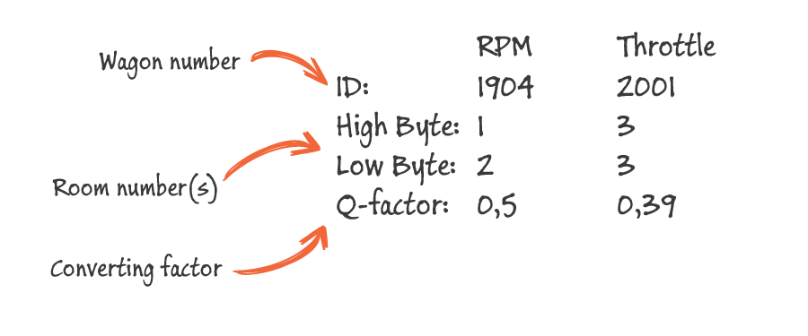
In order to get the signal you are searching for, you need to have an ID, High Byte, Low byte and a quantification factor. The Q-factor is used to convert a message value (unit less) to an understandable value (units such as RPM, V, Bar).
Important information
How many ID’s (wagons) can be on the rails (bus) is depending on many factors. If the bus load exceeds 60-70%, you will get data losses or a crashed train. Also when the rails conditions are not good (bad wiring, no twisted wires etc.), you will get data losses or crashed trains as well. Always make sure that every node (train station) is capable of connecting to the bus (rails). A node which is created for a 500kbit/s rails, cannot be connected to a 1Mbit/s rails.
I know that not every comparison I’ve made in this post is 100% correct, but from personal experience, with explaining CAN basics to others, trying to visualize it, helped them a lot to understand the basics.
Please share, sign up for our newsletter or comment below if you would like to read more of these blogs!
Full acceleration, almost at the RPM limiter, and hit the upshift paddle to change gear… within 80 milli seconds the engine is at full power again, and the next gear is engaged. After you hit the paddle, what happens is not ‘magic’. There is actually a very specific and advanced strategy used to shift pneumatically from one gear to another without using the clutch. Because there is a big difference between up and downshifting, I would like to write and advice only upshifting on this blog.
*In this article I assume you have basic knowledge about sequential gearboxes. If you want to refresh your memory, check this video (10 min.) from Engineering Explained!

RPM Drop
With every upshift the RPM will drop, depending on the ratio of the current and next gear. We will focus on just one upshift, and see what is happening during this time. The gear voltage sensor is a rotary sensor which shows the exact position of the selector barrel.

Stage 1
The up shift always starts with a condition check. There are some safety measures which will avoid initiating an upshift. If for example the driver is off-throttle, an upshift is not performed because there will not be any torque change if an engine cut (ignition interruption) is active (Advanced shift control can handle off-throttle upshift properly).
Stage 2
In this stage the up valve will open. The air hosing will be filled and the shift cylinder will push or pull the gearbox shift lever.
Stage 3
The third stage is called ‘preload time’. This is the time needed to get the shift cylinder on the correct pressure to perform a fast shift. The selector barrel starts to rotate.
Stage 4
Stage four is the power interruption stage. The engine RPM will drop because of the ignition/fuel cut, and the dog ring will be pulled out of gear. The time for this stage is fully dependent on the gearpot voltage. If the next gear is engaged, the next stage will be initiated.
Stage 5
The last stage is called the ‘recovery stage’. During this stage the engine returns to normal operation and the shift cylinder moves back to neutral position. During this stage a new shift is not possible.
All these five stages are usually performed within 50-80 milliseconds. This period is dependent on several factors, for example the RPM drop rate during an engine cut. If the RPM drops too slowly, the dogrings will not match and are unable to engage.
 Data analysis with Bosch Motorsport – Windarab
For the sake of simplicity, I did not mentioned all checks which are being done during each stage. To give you a feeling for milliseconds, I dare you to unlock your phone, open the stopwatch and try to stop it at 80 milliseconds (0,080 seconds). Within that time all stages of the gear-change have occurred and the engine is back to full power..
Please like or share this blog if you would like to read more of these articles!